PSoC5LP Lab 12: DHT11/22, RHT03 Temperature and Humidity Sensor (1-Wire)
Objective
- Understanding Sensor Specifications: Learn the operating voltage, current, output data format, measurement ranges, resolution, accuracy, and sampling rates of the DHT11, DHT22, and RHT03 sensors.
- Implementing 1-Wire Communication: Gain proficiency in the maxdetect 1-Wire communication protocol used by these sensors, including initialization, data transfer, and timing requirements.
- Practical Application: Apply the knowledge gained to interface these sensors with the PSoC5LP microcontroller, enabling accurate temperature and humidity measurements in embedded systems.
Overview
DHT11, DHT22, and RHT03 Sensors
These digital temperature and humidity sensors are commonly used in environmental monitoring projects due to their simplicity and affordability. Although they share similarities, each has unique characteristics:
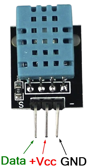
DHT11 Sensor
DHT11 Sensor
Specification:
- Operating Voltage: 3.5V ~ 5.5V
- Operating Current: 0.3mA (measuring), 60μA (Standby)
- Output: 1-Wire Serial Data
- Temperature Range: 0ºC ~ 50ºC
- Humidity Range: 20% ~ 90%
- Resolution: Temperature and Humidity both are 16-bit
- Accuracy: ±1ºC and ±1%
- Sampling Rate: 1 reading every 2 seconds
 |
 |
|
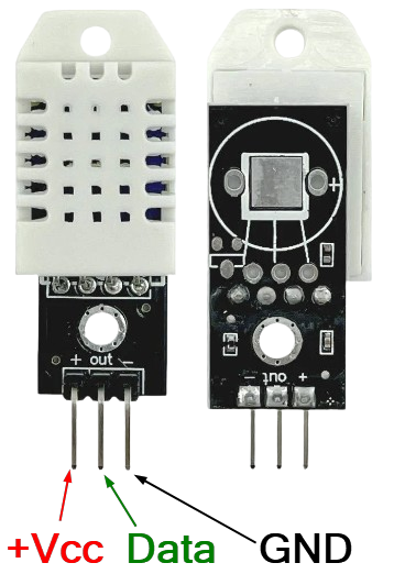
| DHT11 - Temperature and Humidity Sensor | DHT11 Sensor Pinout |
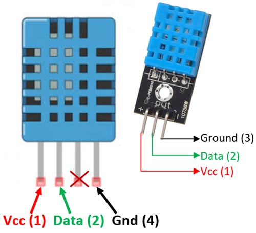
DHT22 Sensor
DHT22 (AM2302) Sensor
The DHT22 is more precise and has a wider range than the DHT11, making it better suited for applications requiring more accuracy or harsher environmental conditions.
Specifications:
- Operating Voltage: 3.5V ~ 5.5V
- Operating current: 0.3mA (measuring) 60μA (standby)
- Output: 1-Wire Serial data
- Temperature Range: -40°C to 80°C
- Humidity Range: 0% to 100%
- Resolution: Temperature and Humidity both are 16-bit
- Accuracy: ±0.5°C and ±1%
- Sampling Rate: 0.5 Hz (2-second interval)
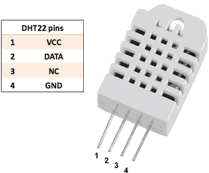
RHT03 Sensor
RHT03 Sensor
Often marketed as equivalent to the DHT22 (or even labeled as AM2302). RHT03 provides comparable accuracy, reliability, and range, often chosen interchangeably with DHT22.
Specifications:
- Operating Voltage: 3.3V ~ 6V
- Operating current: 01~1.5mA (measuring) 40-50μA (standby)
- Output: 1-Wire Serial data
- Temperature Range: -40°C to 80°C
- Humidity Range: 0% to 100%
- Resolution: Temperature and Humidity both are 16-bit
- Accuracy: ±0.5°C and ±2%
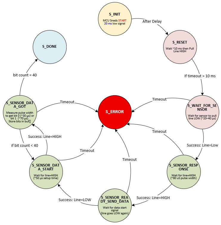
Communication Protocol for DHT Series Sensors
The DHT11, DHT22, and RHT03 use the maxdetect 1-Wire communication protocol. Here is an outline of this protocol:
- Data Line: A single data line is used for communication, where the sensor and microcontroller take turns pulling the line high and low to signal start and data bits.
- Communication Steps:
- Initialization: The microcontroller sends a start signal by pulling the data line low for a specified period.
- Response: The sensor responds with an acknowledgment and then begins sending data.
- Data Transfer: Temperature and humidity data are transmitted as 40-bit messages (8 bits each for humidity, humidity decimal, temperature, temperature decimal, and a checksum).
- Timing Sensitive: The protocol is highly sensitive to timing; thus, precise microcontroller timing (delay functions) is crucial.
The DHT11 sensor is a cost-effective, entry-level sensor that measures temperature from 0 to 50°C with an accuracy of ±2°C and humidity from 20% to 90% with ±5% accuracy. It has a resolution of 1°C and 1% RH, updating approximately once per second. This sensor is well-suited for basic applications and hobby projects where precise readings aren't critical, though it has a limited temperature and humidity range.
The DHT22 offers an extended temperature range from -40 to 80°C and improved accuracy, ±0.5°C for temperature and ±2% for humidity, covering 0% to 100% RH. It has a finer resolution of 0.1°C and 0.1% RH, though it updates every two seconds. The DHT22 is ideal for environmental monitoring applications where higher precision and a broader range are required, though it is slightly more expensive than the DHT11.
The RHT03 (also known as AM2302) is very similar to the DHT22, with the same range, accuracy, and resolution for both temperature and humidity, covering -40 to 80°C and 0% to 100% RH with ±0.5°C and ±2% accuracy, respectively. It also has a 0.1°C and 0.1% RH resolution and updates every two seconds. Like the DHT22, the RHT03 is a reliable choice for applications needing precise environmental readings and is preferred in projects where accuracy and stability are essential.
In summary, the DHT11 is best for simple, low-cost applications, while the DHT22 and RHT03 provide more precise and broader-range measurements, making them suitable for more demanding temperature and humidity monitoring needs.
Required Reading Materials
- Lesson KB 01: Create a PSoC Project using PSoC Creator
- 1-Wire Communications
- Datasheets:
- PSoC Creator Components
Required Components
Circuit / Schematic
Procedure
Creating a New Project
- Launch PSoC Creator.
- Got to File ➤ Open Project ➤ Project/Workspace.
- Open the PSoC5LP workspace in the EE4450 folder.
- After PSoC Creator opens the workspace, right-click on Workspace 'PSoC5LP' in the Workspace Explorer and select Add ➤ New Project….
- Select the correct PSoC5LP device model number, use the "Empty schematic" template, and enter the project name 12_Maxdetect1Wire.
Adding Components in PSoC Creator
Open the "TopDesign.cysch" Schematic File, add the following components:
- Add a Digital Output Pin:
- In the Component Catalog, navigate to Ports and Pins.
- Drag and drop a
 Digital Output Pin onto the schematic.
- Add a Digital Bidirectional Pin:
- Again, under the Ports and Pins catalog.
- Drag and drop the Digital Bidirectional Pin onto the schematic.
- Add a Character LCD component:
- Navigate to the Display catalog in the component selection panel.
- Drag and drop the
 Character LCD onto the schematic.
- Add a Timer component:
- Navigate to the Digital → Functions section.
- Drag and drop a Timer component onto the schematic.
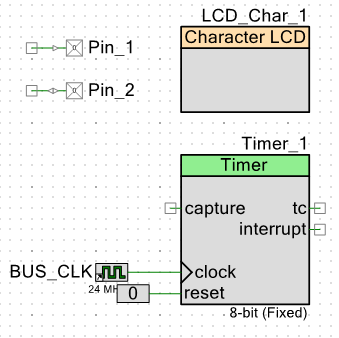
After completing these steps, you have successfully added the Digital Output Pin, a Digital Bidirectional Pin, a Character LCD, and a Timer component to your schematic. You can now proceed to configure each component's parameters and connect them as required for the experiment.
Configure the Components
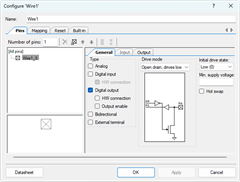
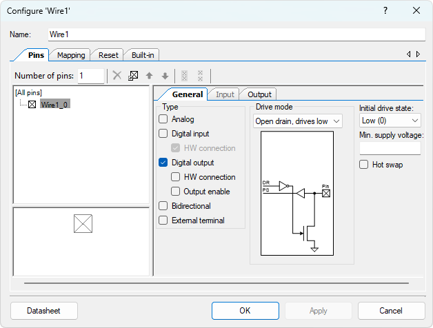
- Configure the Digital Output Pin (Pin_1):
- Click on the Pin_1 component in the schematic.
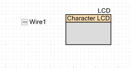
- Rename the component to Wire1 to represent its connection to the 1-wire sensor.
- Uncheck the box for ☐ HW connection to disable the hardware connection. This step ensures that the pin will be controlled manually in the software.
- Change the Drive Mode to the Open drain, drive low mode.
- Configure the Digital Output Pin (Pin_1):
- Click on the Pin_1 component in the schematic.
- Rename the component to Wire1 to represent its connection to the 1-wire sensor.
- Uncheck the box for ☐ HW connection to disable the hardware connection. This step ensures that the pin will be controlled manually in the software.
- Change the Drive Mode to the Open drain, drive low mode.
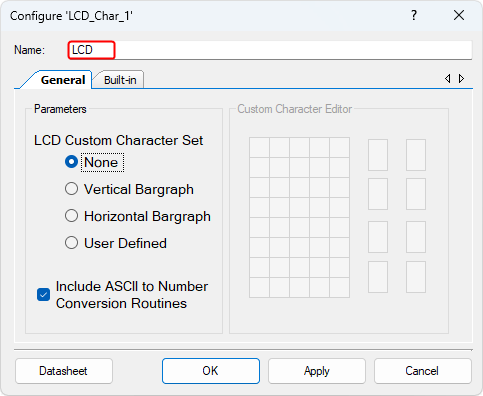
- Config the Character LCD (LCD_Char_1):
- Click on the LCD_Char_1 component in the schematic.
- Rename the component to LCD for clarity and ease of identification.
The new TopDesign.cysch file is shown below:
Pin Assignment
| Device | Port.Pin | Direction | Drive Mode |
|---|---|---|---|
Building the code and Programming
Using the provided firmware code, implement the following functionality:
- Check the temperature and humidity from the sensor every 5 seconds.
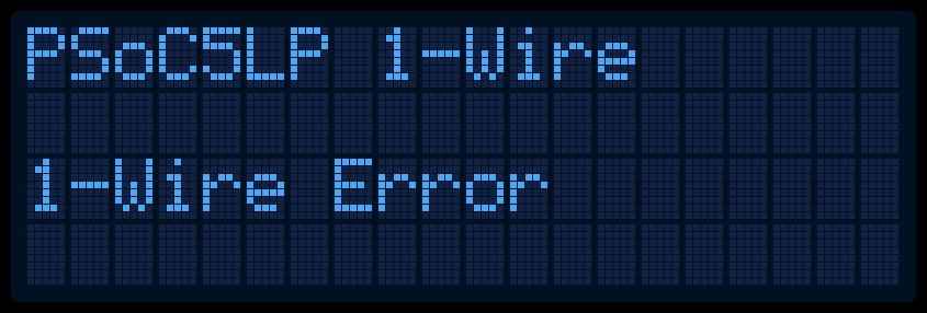
- If Maxdetect_1Wire_Read() returns false, display 1-Wire Error on the LCD screen.
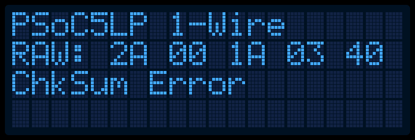
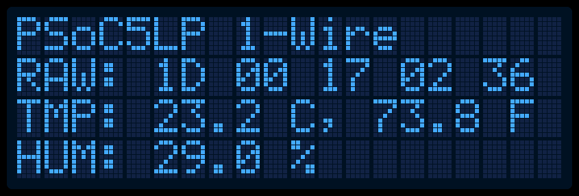
- If Maxdetect_1Wire_Read() returns true, display the raw sensor data in hexadecimal format on the screen.
- If a checksum error occurs, display ChkSum Error on the screen.
- If no errors occur:
- Display the temperature in Celsius (°C) and Fahrenheit (°F) on the LCD screen.
- Display the humidity percentage on the LCD screen.
- Example LCD Screen Layouts as below:
Firmware Code
/* ========================================
 *
 * © 2024 AirSupplyLab. All rights reserved.
 * Unpublished, licensed software.
 *
 * This software contains confidential and proprietary
 * information owned by AirSupplyLab.com.
 *
 * ========================================
*/
#include "project.h"
#include <stdlib.h>
#include <stdio.h>
#include <stdint.h>
#include <stdbool.h>

int8_t      Maxdetect_1Wire_Read(float *tempC, float *hum, uint8_t raw[]);
uint32_t    CalculateTimeUs(uint32_t  timer1, uint32_t timer2);

int main(void)
{
    float   tempC, tempF, hum;
    uint8_t raw[5];
    char    str[40];
    int8_t  errCode;

    CyGlobalIntEnable; /* Enable global interrupts. */

    /* Place your initialization/startup code here (e.g. MyInst_Start()) */
    WIRE1_Write(1);
    TIMER_Start();
    LCD_Start();
    LCD_ClearDisplay();
    LCD_Position(0,0);
    LCD_PrintString("PSoC5LP 1-Wire");
    CyDelay(1000);

    for(;;)
    {
        /* Place your application code here. */
        errCode = Maxdetect_1Wire_Read(&tempC, &hum, raw);
        if ( errCode == 0){
            // No error, display raw, tempC, tempF and hum

        } else if (errCode == -1) {
            // Checksum Error. Display raw and error message

            CyDelay(4000);
        } else {
            // Communication Error, display error message

            CyDelay(4000);
        }
        LED1_Write(!LED1_Read());
        CyDelay(1000);
    }
}
//------------------------------------------------------------------------------
typedef enum STATES{
    S_INIT = 1,                             // Initial state
    S_RESET,                                // Reset state for reinitializing the protocol
    S_WAIT_FOR_SENSOR,                      // Waiting for device response
    S_SENSOR_RESPONSE,                      // Device has responded, ready for data
    S_SENSOR_READY_SEND_DATA,               // Data is ready to be transmitted
    S_SENSOR_DATA_START,                    // Begin data transmission
    S_SENSOR_DATA_GOT,                      // Data has been successfully received
    S_DONE,                                 // Data transmission is complete
    S_ERROR
} ONE_WIRE_STATES;

#define _TS_START_SIGNAL_DURATION    20000   // 20000 us (20 ms): Minimum duration for MCU to send a START signal (at least 18 ms)
#define _TS_RESPONSE_WAIT_TIME       40      // 40 us: Wait time for sensor response (typically 20–40 us)
#define _TS_RESPONSE_SIGNAL_DURATION 80      // 80 us: Duration of sensor's response signal
#define _TS_DATA_INIT_TIME           50      // 50 us: Delay before data transmission starts
#define _TS_DATA_BIT_0_DURATION      30      // 30 us: Duration for a "0" bit (typically 26–28 us)
#define _TS_DATA_BIT_1_DURATION      70      // 70 us: Duration for a "1" bit
#define _TS_LOOP_DELAY               5       // 5 us per loop: Delay for each iteration in timing loops
#define _TS_SIGNAL_TOLERANCE         5       // 5 us: Allowed timing tolerance
#define _TS_TIMING_OFFSET_1WIRE     10
int Maxdetect_1Wire_Read(float *tempC, float *hum, uint8_t raw[])
{
    uint32_t    timer1 = 0;
    uint32_t    timer2;
    int         interval;
    int         bitReceived = 0;
    uint8_t     tmpBuf = 0;
    int         idx = 0;
    uint8_t     checkSum = 0;
    int8_t      errCode = 0;

    ONE_WIRE_STATES  state = S_INIT;
    timer1 = TIMER_ReadCounter();

  while( (state != S_ERROR) && (state != S_DONE) ) {
        timer2 = TIMER_ReadCounter();
        interval = CalculateTimeUs(timer1, timer2);
        switch (state){

            case S_INIT:

                break;
            case S_RESET:

                break;
            case S_WAIT_FOR_SENSOR:

                break;
            case S_SENSOR_RESPONSE:

                break;
            case S_SENSOR_READY_SEND_DATA:

                break;
            case S_SENSOR_DATA_START:

                break;
            case S_SENSOR_DATA_GOT:

                break;
            case S_DONE:

                break;
            case S_ERROR:

                break;
        }
    }

    if (state == S_ERROR)
        return errCode;

    // calculate checksum, temperature, hum

    // For DHT11

    // For DHT21/22

    return 0;
}
//------------------------------------------------------------------------------
// TIMER clock = 10MHz
uint32_t    CalculateTimeUs(uint32_t  timer1, uint32_t timer2)
{
    uint32_t intervalUs;

    return intervalUs;
}

/* [] END OF FILE */
State Diagram